Pumps
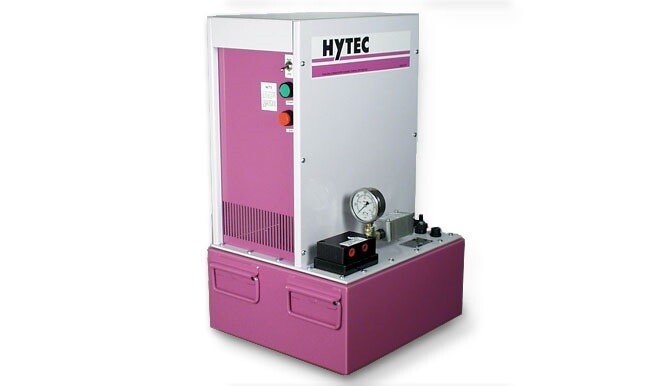
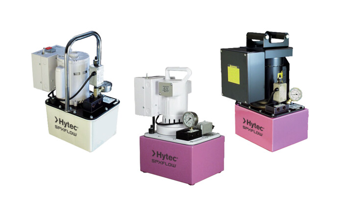
All of Hytec’s electric/hydraulic pumps are two-stage, continuous pressure (demand) pumps that contain all the necessary controls and circuitry for powering any single- or double-acting, continuous pressure workholding system. They contain a pressure switch and pressure regulator, and each is infinitely adjustable throughout the operating pressure range of 1,000 to 5,000 psi. An internal safety relief valve prevents possible damage from exceeding the maximum rated pressure.
The first stage provides high flow at low pressure to rapidly extend clamps and cylinders. The second stage piston pump builds and maintains pressure in the system at a preset level.
The pumps’ electrical controls include a RUN/JOG switch. When the pump is started in the RUN mode, it automatically starts and runs any time the pressure switch indicates the need for oil. When pressure builds to the switch setting, the pump stops until the next demand for oil lowers the pressure, causing the switch to start the pump again. The pump continues to cycle in this manner without operator intervention.
In the JOG mode, useful for set up and special applications, the pump will run only when the operator activates and holds the start switch. When released, the pump will stop immediately. If the pump builds pressure to the pressure switch setting, it will also stop. The pump cannot be forced to run after the pressure switch setting has been reached in either the RUN or the JOG mode.
Pumps having thermal overload protection have an integral “electrical shut-down” circuit which prevents the pump from restarting without manual intervention after either thermal overload or electrical service interruption. Motor electrical specifications are listed for each pump. For voltages and frequencies not listed, contact Hytec for more information.
View Catalog - Electric/Hydraulic Pumps
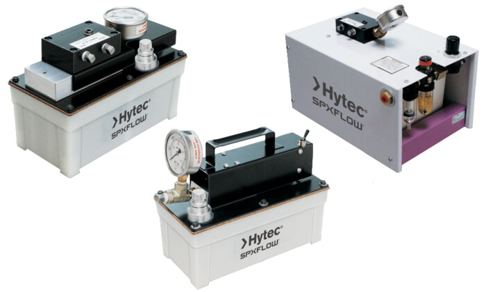
Hytec’s air/hydraulic pumps are all continuous pressure, reciprocating, stalltype pumps: air pressure is simply converted to hydraulic pressure. Operated by any compressed air source, these pumps save energy by stalling when pressure is developed, and require no energy use to maintain system pressure. Single- and two-stage pumps are available.
Pumps of this type typically have much more usable oil capacity than ordinary boosters. Boosters stop after only one stroke, and if pressure is not built by the end of the stroke, or if any leakage is present, system pressure will not be maintained. Hytec air/hydraulic pumps will maintain pressure levels because they continue to reciprocate until pressure develops. Once pressure is developed, the pump stalls and maintains consistent system pressure. If additional flow is necessary for maintaining pressure, the pump will again reciprocate any time the end of its stroke is reached.
These pumps all operate within an air pressure range of 40-125 psi. Hydraulic operating pressures range from 400-5,000 psi.
Selected Hytec air/hydraulic pumps come with an air supply filter/lubricator/regulator for making hydraulic pressure adjustments. There is even a version that includes a selector valve and the circuitry required to provide control of single acting circuits without the need for additional directional control valves.
View Catalog - Air/Hydraulic Pumps
Features
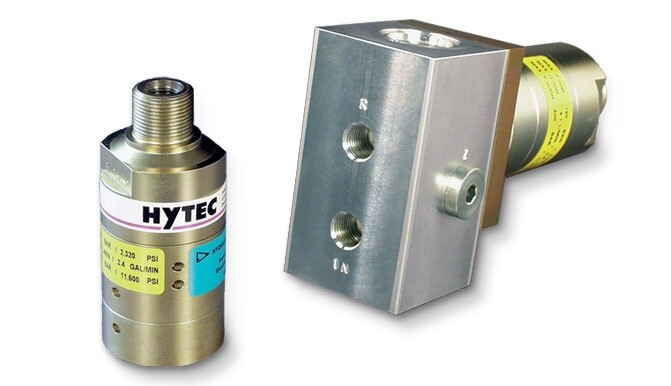
Intensifiers are used in applications where an existing low pressure hydraulic source is available. They amplify low pressure to a range better suited to work holding systems.
Intensifiers use a reciprocating pumping mechanism to generate the high pressure flow so their volume is not limited as with piston style intensifiers. This allows the intensifier to compensate for any oil consumption on the high pressure side. The outlet pressure is directly proportional to the inlet pressure. High pressure adjustment is achieved by varying the inlet pressure.
Flow from the low pressure source is directed through the intensifier to the downstream circuit. As system pressure increases, the intensifier begins to cycle and intensifies the system pressure by the ratio specified.
Models without a dump valve do not allow reverse flow so directional control must take place downstream in the high pressure circuit. Models with the dump valve allow directional control in the low pressure supply circuit. The optional directional valve manifold block has a standard Vickers C-10-4 cavity to accept a variety of manual and solenoid valves. Fitting No. 253288 can be used with part No. 100997. See Fittings for specifications.
- 5,000 psi maximum
- 3.2, 4 and 5.1 ratios available
- Optional valve manifold
- Extremely compact size
View Catalog - Intensifiers - 100991-100993/100997 ‖ US