Universal 2 Series - AP (Automotive Paint) - Positive Displacement Pumps
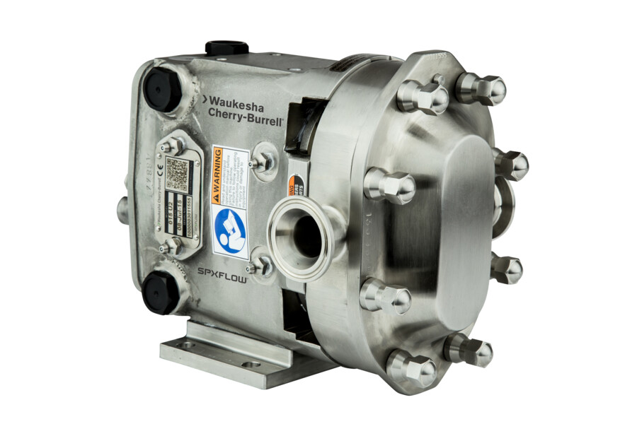
This positive displacement pump is manufactured specifically for paint re-circulation in the automotive industry.
FEATURES
A modification of the Universal 2 positive displacement pump, this pump is manufactured specifically for paint re-circulation in the automotive industry. Features:
- 316 stainless steel pump body and cover.
- Exclusive, non-galling Waukesha “88” alloy rotors standard; permits running at tighter clearances and pumping a wide range of viscosities.
- Rotor/shaft connection sealed from product zone.
- Mechanical seals standard. Single or flushed double.
- Up to 500 psi (34.5 bar) pressure capability.
- Rotor nut designed for extended service without loosening.
- No bearings in product zone.
- Larger diameter 17-4 PH shafts in seal area for greater strength and stiffness. Helps eliminate vibration; extends seal life.
- Heavy duty bearing frame.
- Double tapered roller bearings on all models. Contribute further to precise rotor position and longer seal life.
- Silicone free grease lubed bearings for positive lubrication to all bearings over entire speed, temperature and pressure range.
- Body retaining screws for maintaining mechanical seal contact during inspection.
- O-ring on inner seal, seals on clean surface as seal moves due to wear.
- Bearing isolators keep product out of gearcase and bearings.
Benefits:
- Protects water-borne shear sensitive paints.
- Pigments are not separated, which can change viscosity and cause color shifts.
- Aluminum and mica metallic flakes are not damaged, which result in deep rich paint luster, and shiny finish.
- Color matching between body and components is not a problem.
- Substantial energy cost savings compared to turbine and piston pumps.
- Constant flow regardless of system pressure changes, results in high film quality and thickness.
- Pressure surges eliminated.
- Minimal heat added to product.
- Pumps are energy efficient, and easily cleaned, maintained, and repaired.
Pump Comparisons:
Eliminates surge suppression
Constant flow regardless of system pressure changes
Minimal heat input
Variable speed drive options
Energy efficient
Easily repaired
Easily maintained
Prevent metallic flake degradation
Time-tested Waukesha Cherry-Burrell® rotary pump; circumferential-piston operating principle
In the Waukesha Cherry-Burrell design, arc-shaped "pistons” (rotor wings) travel in annular-shaped cylinders machined in the pump body; the resulting long sealing path reduces slippage and produces a smooth flow of product without destructive pulses or pressure peaks and without valves or complex parts.


FOR LOW VISCOSITY FLUIDS
Rotors, made of Waukesha “88” alloy, can be run with close clearance to the 316L stainless steel fluid head, without galling or seizing should inadvertent pressure surges cause contact. The close clearances combined with the rotor geometry, which gives a long sealing path between the pump inlet and outlet, means low slip operation. As a result, you achieve: high efficiency, good priming ability, metering capability and good flow control.

FOR HIGH VISCOSITY FLUIDS
The large fluid cavities of the rotors ... plus the large, easy entry anti-cavitation ports, allow efficient pumping of high viscosity fluids, slurries or even liquids with large chunks or
particles.


FOR NON-LUBRICATING AND ABRASIVE FLUIDS
The Waukesha Cherry-Burrell design has no bearings in the fluid being pumped, no sliding or rolling contact and no rotor-to-rotor contact. This produces EXCELLENT SERVICE LIFE even under severe operating conditions.


DIMENSIONS & SPECIFICATIONS
Model AP 015-U2
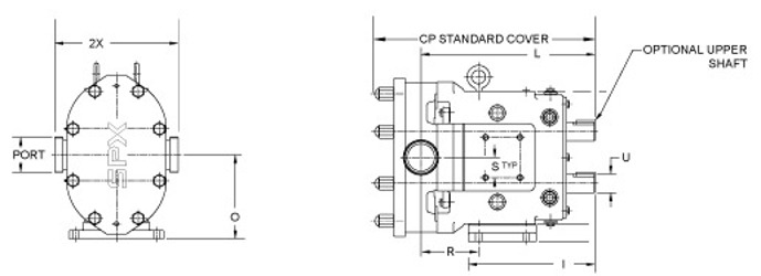
| CP | I | L | O | PORT SIZE | U +.000-.001 | 2X | |
|---|---|---|---|---|---|---|---|
| IN | 11.71 | 7.66 | 9.61 | 4.21 | 1-1/2" | 0.875 | 6.97 |
| MM | 297 | 194 | 244 | 107 | ----- | 22.23 | 177 |
NOTE: Dimension “2X” applies for “S”-Clamp on Models 015 through 220. D I N and other connections available. Dimension “2X” applies for 6” (152 mm) 150 lb. RF Flange on Model 320.
Model AP 018-U2
| CP | I | L | O | PORT SIZE | U +.000-.001 | 2X | |
|---|---|---|---|---|---|---|---|
| IN | 12.37 | 7.66 | 10.48 | 4.21 | 1-1/2" | 0.875 | 6.97 |
| MM | 314 | 194 | 266 | 107 | ----- | 22.23 | 177 |
NOTE: Dimension “2X” applies for “S”-Clamp on Models 015 through 220. D I N and other connections available. Dimension “2X” applies for 6” (152 mm) 150 lb. RF Flange on Model 320.
Model AP 030-U2
| CP | I | L | O | PORT SIZE | U +.000-.001 | 2X | |
|---|---|---|---|---|---|---|---|
| IN | 14.49 | 8.83 | 11.61 | 5.21 | 1-1/2" | 1.25 | 8.5 |
| MM | 368 | 224 | 295 | 132 | ----- | 31.75 | 216 |
NOTE: Dimension “2X” applies for “S”-Clamp on Models 015 through 220. D I N and other connections available. Dimension “2X” applies for 6” (152 mm) 150 lb. RF Flange on Model 320.
Model AP 040-U2
| CP | I | L | O | PORT SIZE | U +.000-.001 | 2X | |
|---|---|---|---|---|---|---|---|
| IN | 14.87 | 8.83 | 11.77 | 5.21 | 2" | 1.25 | 8.62 |
| MM | 378 | 224 | 305 | 132 | ------ | 31.75 | 219 |
NOTE: Dimension “2X” applies for “S”-Clamp on Models 015 through 220. D I N and other connections available. Dimension “2X” applies for 6” (152 mm) 150 lb. RF Flange on Model 320.
Model AP 045-U2
| CP | I | L | O | PORT SIZE | U +.000-.001 | 2X | |
|---|---|---|---|---|---|---|---|
| IN | 18.59 | 10.99 | 14.86 | 7.31 | 2" | 1.625 | 10.75 |
| MM | 472 | 279 | 377 | 186 | ----- | 41.28 | 273 |
NOTE: Dimension “2X” applies for “S”-Clamp on Models 015 through 220. D I N and other connections available. Dimension “2X” applies for 6” (152 mm) 150 lb. RF Flange on Model 320.
Model AP 060-U2
| CP | I | L | O | PORT SIZE | U +.000-.001 | 2X | |
|---|---|---|---|---|---|---|---|
| IN | 19.14 | 10.99 | 15.14 | 7.31 | 2-1/2" | 1.625 | 10.75 |
| MM | 486 | 279 | 385 | 186 | ----- | 41.28 | 273 |
NOTE: Dimension “2X” applies for “S”-Clamp on Models 015 through 220. D I N and other connections available. Dimension “2X” applies for 6” (152 mm) 150 lb. RF Flange on Model 320.
Model AP 130-U2
| CP | I | L | O | PORT SIZE | U +.000-.001 | 2X | |
|---|---|---|---|---|---|---|---|
| IN | 20.15 | 10.99 | 15.77 | 7.31 | 3" | 1.625 | 10.75 |
| MM | 512 | 279 | 401 | 186 | ----- | 41.28 | 273 |
NOTE: Dimension “2X” applies for “S”-Clamp on Models 015 through 220. D I N and other connections available. Dimension “2X” applies for 6” (152 mm) 150 lb. RF Flange on Model 320.
Model AP 180-U2
| CP | I | L | O | PORT SIZE | U +.000-.001 | 2X | |
|---|---|---|---|---|---|---|---|
| IN | 23.26 | 14.8 | 18.25 | 9.38 | 3" | 2 | 13.06 |
| MM | 591 | 376 | 464 | 238 | ------ | 50.8 | 332 |
NOTE: Dimension “2X” applies for “S”-Clamp on Models 015 through 220. D I N and other connections available. Dimension “2X” applies for 6” (152 mm) 150 lb. RF Flange on Model 320.
Model AP 210-U2
| CP | I | L | O | PORT SIZE | U +.000-.001 | 2X | |
|---|---|---|---|---|---|---|---|
| IN | 27.08 | 17.8 | 21.24 | 10.38 | 4" | 2.375 | 14.73 |
| MM | 688 | 452 | 539 | 264 | ------ | 60.45 | 374 |
NOTE: Dimension “2X” applies for “S”-Clamp on Models 015 through 220. D I N and other connections available. Dimension “2X” applies for 6” (152 mm) 150 lb. RF Flange on Model 320.
Model AP 220-U2
| CP | I | L | O | PORT SIZE | U +.000-.001 | 2X | |
|---|---|---|---|---|---|---|---|
| IN | 24 | 14.8 | 18.49 | 9.38 | 4" | 2 | 13.25 |
| MM | 610 | 376 | 470 | 238 | ----- | 50.8 | 337 |
NOTE: Dimension “2X” applies for “S”-Clamp on Models 015 through 220. D I N and other connections available. Dimension “2X” applies for 6” (152 mm) 150 lb. RF Flange on Model 320.
Model AP 320-U2
| CP | I | L | O | PORT SIZE | U +.000-.001 | 2X | |
|---|---|---|---|---|---|---|---|
| IN | 27.66 | 17.8 | 21.63 | 10.38 | 6 150# FLG | 2.375 | 16 |
| MM | 703 | 452 | 549 | 264 | ----- | 60.45 | 406 |
NOTE: Dimension “2X” applies for “S”-Clamp on Models 015 through 220. D I N and other connections available. Dimension “2X” applies for 6” (152 mm) 150 lb. RF Flange on Model 320.