DP4 – Piggable Valve

Product Type(s) : Mixproof Valves
Description :

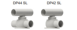
Piggable valves enable you to recover costly products out of product lines.  Once the pig is forced through the line, the remaining product film on the inside of the product line can then be removed with much less CIP fluid which lowers the amount of wastewater, cleaning fluids and cleaning time. They are particularly well suited in processing viscous fluids.
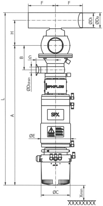
WHERE TO BUY

FEATURES

High value, Low life cycle costs:

  • Pig use enables valuable product recovery
  • Pig use decreases downtime related to cleaning, and the costs associated with wastewater and CIP fluid
  • Reduced inventory costs with same seal kit used on multiple size ranges such as one kit for 1.5” - 3.0” sizes
  • Low air consumption and air supply requirements
  • Leak drain with clamp connection for CIP fluid collection
  • Long housing ports ease manifold building

Reliable performance:

  • Design based on the proven D4SL model
  • Long stroke for gentle product handling and low flow resistance
  • Balanced design of lower shafts helps to prevent hydraulic blocking and enables flexible flow direction without slamming
  • Heavy-duty bolted flange connection provides secure, controlled assembly/disassembly of valve insert
  • No compressed air needed for removal and servicing
  • Range of control units and bus communication for automated operation

Cleanability:

  • Designed to the latest global hygienic standards
  • Extensive cleaning of product contact seals via seat lifting of upper and lower shaft
  • Cavity spray cleaning as standard
  • Radial seal design provides minimal switching leakage
  • External flushing of outside area of the lower shaft below the shaft seal


Theory of Operation

How do double seat piggable valves work?


Double seat piggable valves are used to safely process two different fluids efficiently (typically product and CIP) through the valve simultaneously.  The DP4 mixproof design has two independently operating seats that separate the upper and lower pipeline when the valve is in the fail safe closed position.  The atmospheric vent cavity between the seats creates a path to exit through the leakage chamber should the seals fail, as well as a drain for CIP solution during seat cleaning. External CIP spray flush connections are included to provide enhanced cleaning of the leakage vent cavity as well as the lower shaft, while the valve is closed or open during production.

Product in Blue:


CIP Solution in Yellow:


Valve Closed:


The lower and upper valve shafts are in closed position and safely separate the different liquids A and B. The leakage chamber L, which is situated between the two valve shafts, provides for a free and depressurized discharge to the drain housing. The lower valve shaft is balanced and, thereby, protected against pressure hammer.

Valve Open:


The middle seal in the upper valve shaft is pressed against the lower valve shaft by control of the actuator. First, the leakage chamber L is closed against the product chamber. Then the two valve shafts move downwards into the open position. The connection between pipelines A and B is established.

Key Applications

Food and Drink Processing

Soups & Sauces
Flavorings & Ingredients
Dressings, Vinegars
Soft/Fruit & Vegetable Drinks
Brewery, Wort, Wine
Pet Food
Fats & Oils, Animal Oils
Liquid Sugar
Cereals

Personal Care and Pharmaceutical Processing

Fluid Medicines
Extracts
Face Creams & Lotions
Perfumes
Soaps
High Purity Water
Nutritional Supplements
Hair Styling Gels & Liquids
Dyes & Alcohols

Chemical Processing

Solvents, Paints
Adhesives
Coatings
Oils & Lubricants
Detergents
Emulsions
Fuels

DIMENSIONS & SPECIFICATIONS


Dimensions in mm

inst.

dim.

weights in kg

with VPI

DN

A1

B

Ø C

Ø Da

Ø Di

Ø Di drain

Ø E

F

G

H

L

X min.

40

602,6

97

134

41

38

26

138,2

125

89,5

93

716,1

100

21,2

50

620,6

103

134

53

50

26

138,2

125

89,5

101,5

748,6

100

21,5

65

638,6

111

134

70

66

26

138,2

125

89,5

114,5

788,1

100

22,5

80

706,1

122,5

134

85

81

38

192,2

142,5

146,5

135

883,6

150

39,7

100

715,6

132

134

104

100

38

192,2

142,5

146,5

149,5

917,1

150

39,9

Inch


1,5"

601

95,4

134

38,1

34,9

26

138,2

125

89,5

94,1

714,2

100

21,2

2"

619,4

101,8

134

50,8

47,6

26

138,2

125

89,5

102,6

747,4

100

21,5

2,5"

635,8

108,15

134

63,5

60,3

26

138,2

125

89,5

109,4

776,9

100

22,1

3"

642,1

114,45

134

76,1

72,9

26

138,2

125

89,5

118,5

798,6

100

22,3

4"

714,4

130,8

134

101,6

97,6

38

192,2

142,5

146,5

152

917,2

150

40

Sizes: 1.5" - 4" Housing Types: DP44 & DP42 Surfaces:  

  • Inside: electropolished Ra 0.8 µm (32 µ-in) with Electropolish
  • Outside: Glass-blasted, satin finish

Product Pressure: 

  • Max. Pipeline: 145 psi
  • Tank Holding: >73 psi

Required Air Pressure: 73 psi, valve normally closed Max. Temperature: EPDM & HNBR: 275ºF (for short time 284ºF) FPM 275ºF (not to be used for steam) Sterilization Temperature:  EPDM & HNBR: (for short time) 284ºF Control Air Pressure: Min. 87 psi, max. 116 psi Product Wetted Parts: 1.4404/AISI 316L.  Other stainless steel parts 1.4301/AISI 304 Seal Material:

  • EPDM
  • HNBR
  • FPM
  • All seals comply with the FDA requirements

OPTIONS & PERFORMANCE

Housing Combinations


Control Units

CU4 & CU4plus Series - Benefits

  • Automated control and position monitoring for reliable processing
  • Reduces compressed air needs and electrical connections
  • Helps reduce external solenoid valve cabinets
  • Accelerates valve response time
  • Reliable and long service life - robust clamp connection, water tight seals and reinforced stainless steel air coupling threads to avoid air leakages
  • Ease of operation - contains manual override solenoids and adjustment screw to throttle air flow to actuator to ensure optimal opening and closing
  • Clarity - clear and bright indication of valve position - 5 diodes in LED panel and convenient location
  • Standardization - same control top used on various SPX FLOW valve lines, offers common look and control interface
  • NEMA6/IP67/IP69k* wash-down rating

CONNECTOR OPTIONS

S/O Cord Grip for hard wire (std)
M12 pin connectors (optional)

POSITION INDICATION

CU4: 2 internal feedback sensors for valve open/valve closed position detection
CU4plus: Automatic teaching with press of a single button and detection of all positions (open, close, upper/lower seat lifts)

INTERFACE OPTIONS

24V DC Direct Connect
AS-i Field Bus Card

SOLENOID VALVES

24V DC
3 Solenoids (seat lift)

*IP69K compliance achieved by modification of the exhaust

Downloads