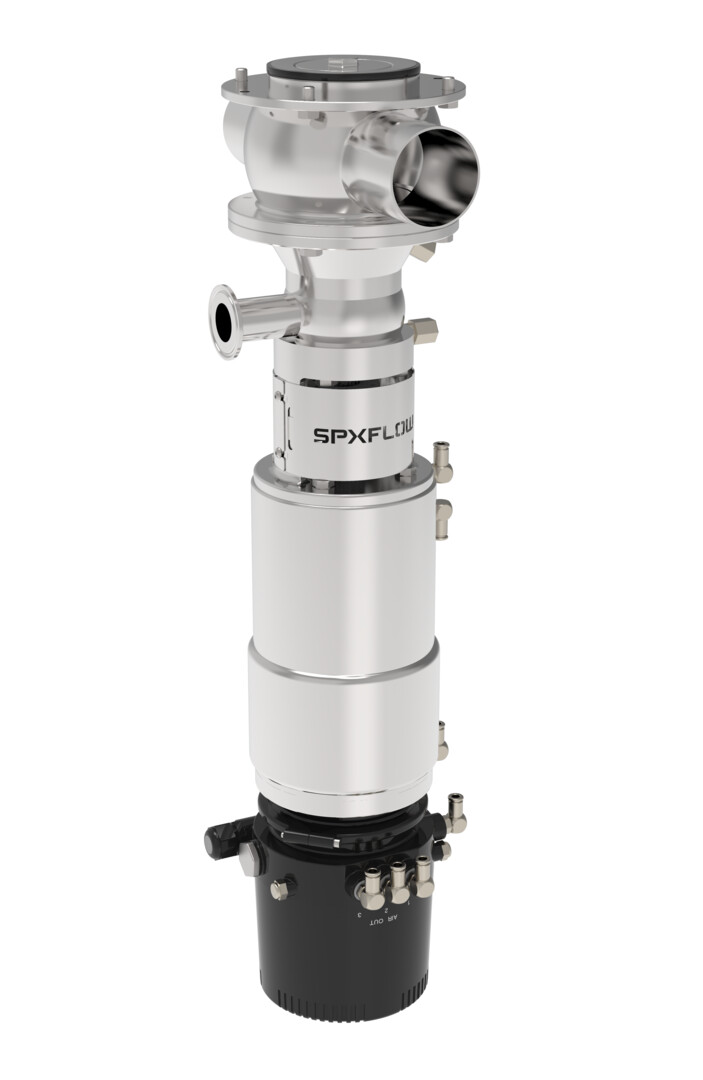
DT4 - Tank Outlet Double Seat Mixproof Valves

Product Type(s) : Tank Outlet Valves
Description :

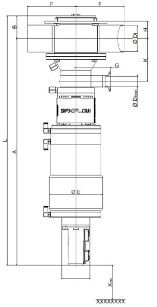
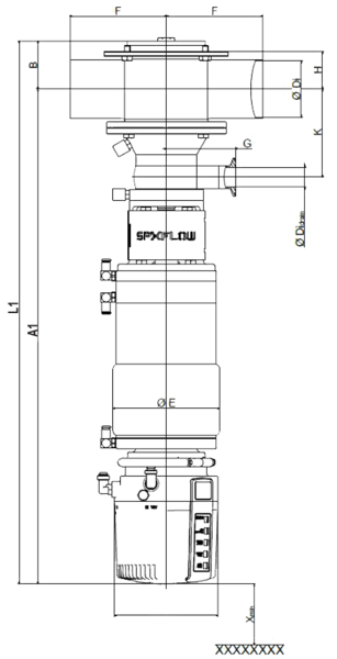
The DT4 tank outlet mix proof valve is used for the reliable separation between the tank and servicing pipeline. The DT4 tank outlet is an extension to the D4 Series mix proof family which helps fulfil today’s customer demands for production flexibility, increased productivity, rapid return on investment (ROI) and improved product quality in the food and drink, dairy, personal care and brewing process industries.

WHERE TO BUY

FEATURES

High value, Low life cycle costs:

  • “All-In” standard features such as seat lift actuator and cross-port housing provide exceptional value
  • Reduced inventory costs with same seal kit used on multiple size ranges: DN40-DN65 (1.5”-3.0”) and DN80-DN100 (4.0”)
  • Low air consumption and air supply requirements
  • Leak drain with clamp connection for CIP fluid collection
  • Long housing ports ease manifold building
  • Integrated shaft seal flush reduces need for external piping

Reliable performance:

  • Design based on the proven D4SL model
  • Tank side holding pressure greater than 5 bar (73 PSI)
  • Long stroke for gentle product handling (ex: particulates) and low flow resistance
  • Balanced design helps to prevent hydraulic blocking and enables flexible flow direction without slamming
  • Heavy-duty bolted flange connection between tank/housing/insert provides secure, controlled assembly/disassembly of valve insert
  • No compressed air needed for removal and servicing
  • Range of control units and bus communication for automated operation

Cleanability:

  • Designed to the latest global hygienic standards
  • Cavity spray cleaning as standard
  • Radial seal design provides minimal switching leakage
  • Extensive cleaning of product contact seals

View the SPXFLOW D4 Mix Proof Valve Maintenance (Chinese) video.

Theory of Operation

How do tank outlet valves work ?


Double seat mix proof valves are used to safely process two different fluids efficiently (typically product and CIP) through the valve simultaneously. The DT4 mix proof design has two independently operating seats that separate the tank and pipeline when the valve is in the fail-safe closed position. The atmospheric vent cavity between the seats creates a path to exit through the leakage chamber should the seals fail, as well as a drain for CIP solution during seat cleaning. External CIP spray flush connections are included to provide enhanced cleaning of the leakage vent cavity as well as the lower shaft, while the valve is closed or open during production.


Product in Blue


CIP Solution in Yellow


Valve Closed

Optional Lower Seat Clean

Valve Open


Optional Upper Seat Clean

Key Applications

Food and Drink Processing

Soups & Sauces
Flavorings & Ingredients
Dressings, Vinegars
Soft/Fruit & Vegetable Drinks
Brewery, Wort, Wine
Pet Food
Fats & Oils, Animal Oils
Liquid Sugar
Cereals

Personal Care and Pharmaceutical Processing

Fluid Medicines
Extracts
Face Creams & Lotions
Perfumes
Soaps
High Purity Water
Nutritional Supplements
Hair Styling Gels & Liquids
Dyes & Alcohols

Chemical Processing

Solvents, Paints
Adhesives
Coatings
Oils & Lubricants
Detergents
Emulsions
Fuels

DIMENSIONS & SPECIFICATIONS

Dimensions mm A A1 B øDi

øDi

Drain

øE F G H K L L1 X*
DN                          
40 551,2  602,6  45 38 26 138,2 125 89,5  31 97 596,2  647,6  100
50 569,2  620,6  51 50 26 138,2 125 89,5  37 103 620,2  671,6  100
65 587,2  638,6  59 66 26 138,2 125 89,5  45 111 646,2  697,6  100
80 654,6  706 67,5  81 26 192,2 142,5  146,5  51,5  122,5  722,1  773,5  100
100 664,1  715,5  77 100 26 192,2 142,5  146,5  61 132 741,1  792,5  100
INCH                          
1.5 549,6  601 46,6  34,8  26 138,2 125 89,5  32,6  95,4  596,2  647,6  100
2.0 568 619,4  52,2  47,6  26 138,2 125 89,5  38,2  101,8  620,2  671,6  100
2.5 584,35  635,75  56,15  60,3  26 138,2 125 89,5  42,15  108,15  640,5  691,9  100
3.0 590,65  642,05  62,45  72,9  26 138,2 125 89,5  48,45  114,45  653,1  704,5  100
4.0 662,9  714,3  78,2  97,6  26 192,2 142,5  146,5  62,2  130,8  741,1  792,5  100

*Minimum installation and valve insert removal dimensions

Sizes: 1.5" - 4" DN40 - DN100 Housing Types: T42 Surfaces:  

  • Inside: electropolished Ra 0.8 µm (32 µ-in) with Electropolish
  • Outside: Glass-blasted, satin finish

Product Pressure: 

  • Max. Pipeline:  10 Bar (145 psi)
  • Tank Holding:  >5 bar (73 psi)

Required Air Pressure: 5 bar (73 psi), valve normally closed Max. Temperature: EPDM & HNBR: 135ºC/275ºF (for short time 140ºC/284ºF) FPM 135ºC/275ºF (not to be used for steam) Sterilization Temperature:  EPDM & HNBR: (for short time) 140ºC/284ºF Control Air Pressure: Min. 87 psi (6 bar), max. 116 psi (8 bar) Product Wetted Parts: 1.4404/AISI 316L.  Other stainless steel parts 1.4301/AISI 304 Seal Material:

  • EPDM
  • HNBR
  • FPM
  • All seals comply with the FDA requirements

OPTIONS & PERFORMANCE

Housing Combinations


DT42


Control Units

CU4 & CU4plus Series - Benefits

  • Automated control and position monitoring for reliable processing
  • Reduces compressed air needs and electrical connections
  • Helps reduce external solenoid valve cabinets
  • Accelerates valve response time
  • Reliable and long service life - robust clamp connection, water tight seals and reinforced stainless steel air coupling threads to avoid air leakages
  • Ease of operation - contains manual override solenoids and adjustment screw to throttle air flow to actuator to ensure optimal opening and closing
  • Clarity - clear and bright indication of valve position - 5 diodes in LED panel and convenient location
  • Standardization - same control top used on various SPX FLOW valve lines, offers common look and control interface
  • NEMA6/IP67/IP69k* wash-down rating

CONNECTOR OPTIONS

S/O Cord Grip for hard wire (std)
M12 pin connectors (optional)

POSITION INDICATION

CU4: 2 internal feedback sensors for valve open/valve closed position detection
CU4plus: Automatic teaching with press of a single button and detection of all positions (open, close, upper/lower seat lifts)

INTERFACE OPTIONS

24V DC Direct Connect
AS-i Field Bus Card

SOLENOID VALVES

24V DC
Select 1 (non-seat lift) or 3 Solenoids (seat lift)

*IP69K compliance achieved by modification of the exhaust

VIDEOS

Downloads