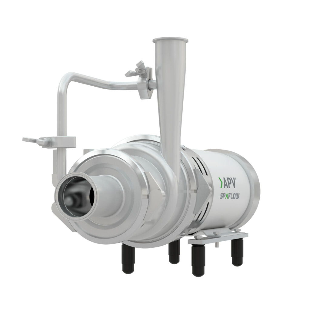
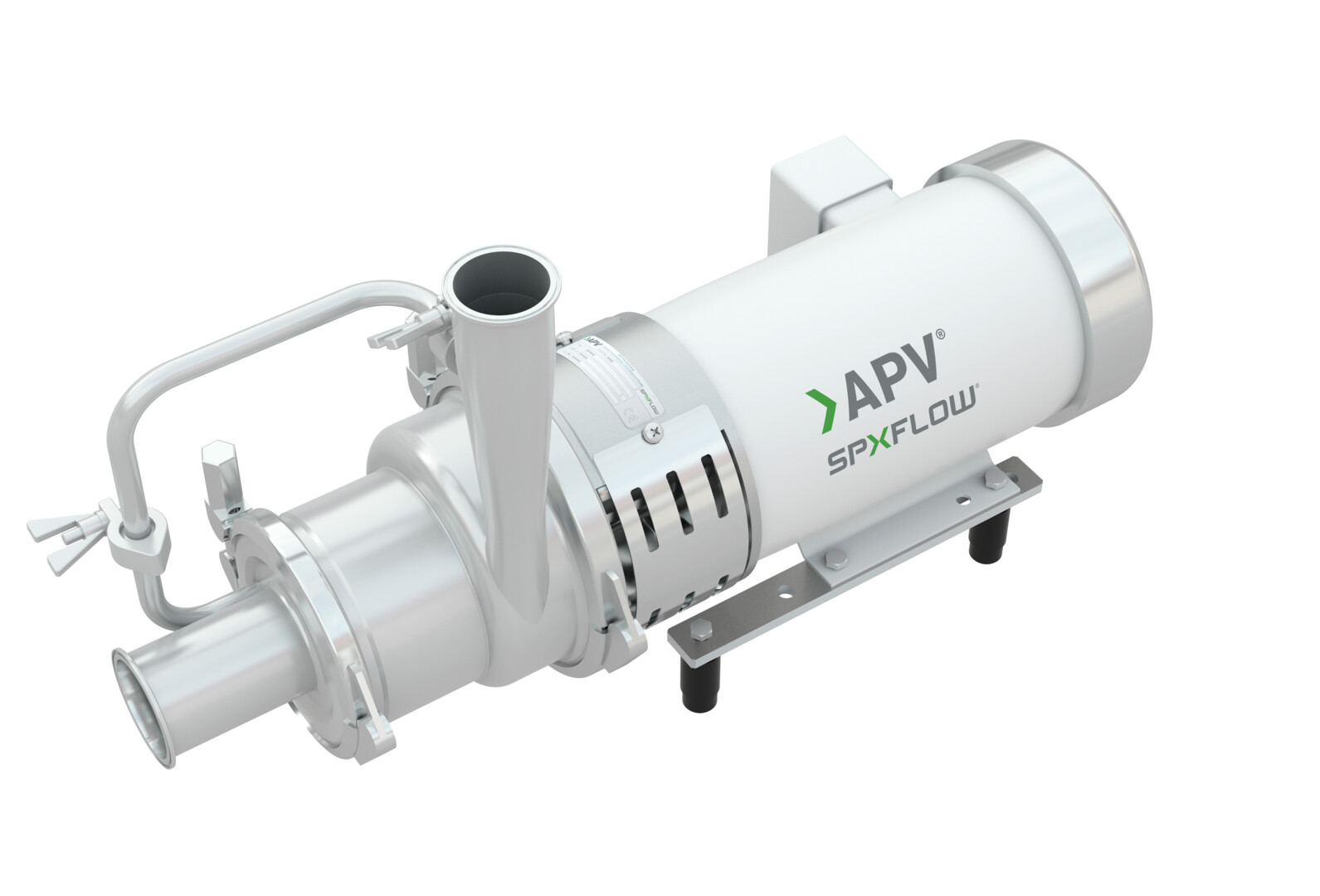
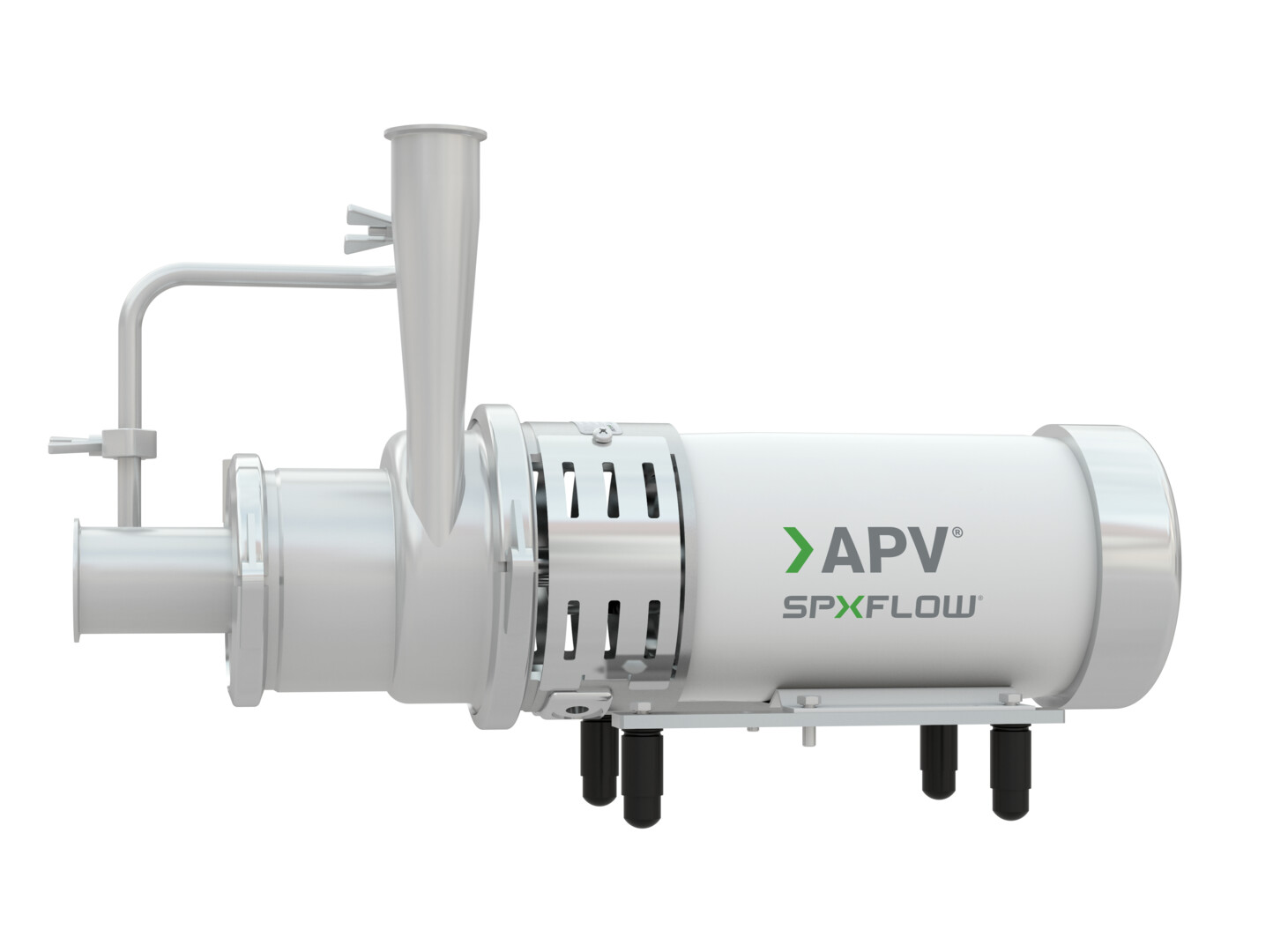
Ws+ Series (NEMA) - Self-Priming Centrifugal Pumps

Product Type(s): Centrifugal Pumps
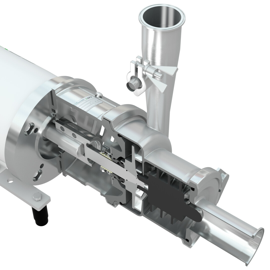
The Ws+ uses a unique design that combines the abilities of most liquid ring pumps with the efficiencies of the W+ centrifugal series. As a result customers can now handle entrained air and lift requirements with lower horsepower, less noise and at lower cost.
Model 20/15
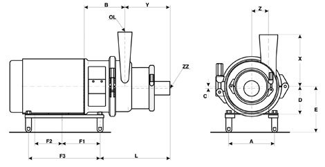
| Unit Width Height | ||||||||||||||
|---|---|---|---|---|---|---|---|---|---|---|---|---|---|---|
| FRAME | F1 in (mm) |
F2 in (mm) |
F3 in (mm) |
D in (mm) |
A in (mm) |
E in (mm) |
L in (mm) |
C in (mm) |
B in (mm) |
ZZ in (mm) |
OL in (mm) |
Z in (mm) |
X in (mm) |
Y in (mm) |
| 145TC | 3.75 (93.5) |
5.00 (127) |
10.25 (260.4) |
3.50 (88.9) |
5.50 (139.7) |
7.00 (177.8) |
9.46 (240) |
0.315 (8) |
5.98 (152) |
2.5 (63.5) |
2.0 (51.6) |
2.60 (66) |
8.47 (215) |
4.48 (190) |
| 182TC | 4.37 (111) |
4.50 (114.3) |
11.37 (288.8) |
4.50 (114.3) |
7.50 (190.5) |
8.00 (203.2) |
9.87 (250) |
7.01 (178) |
||||||
| 184TC | 5.50 (139.7) |
|||||||||||||
NOTE: Dimensions are for guidance purposes only. Contact your SPX FLOW representative if more detailed measurements are needed.