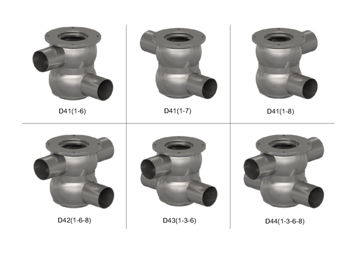
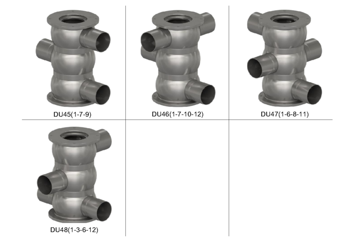
D4 / DA4 Series - Double Seat Mixproof Valves
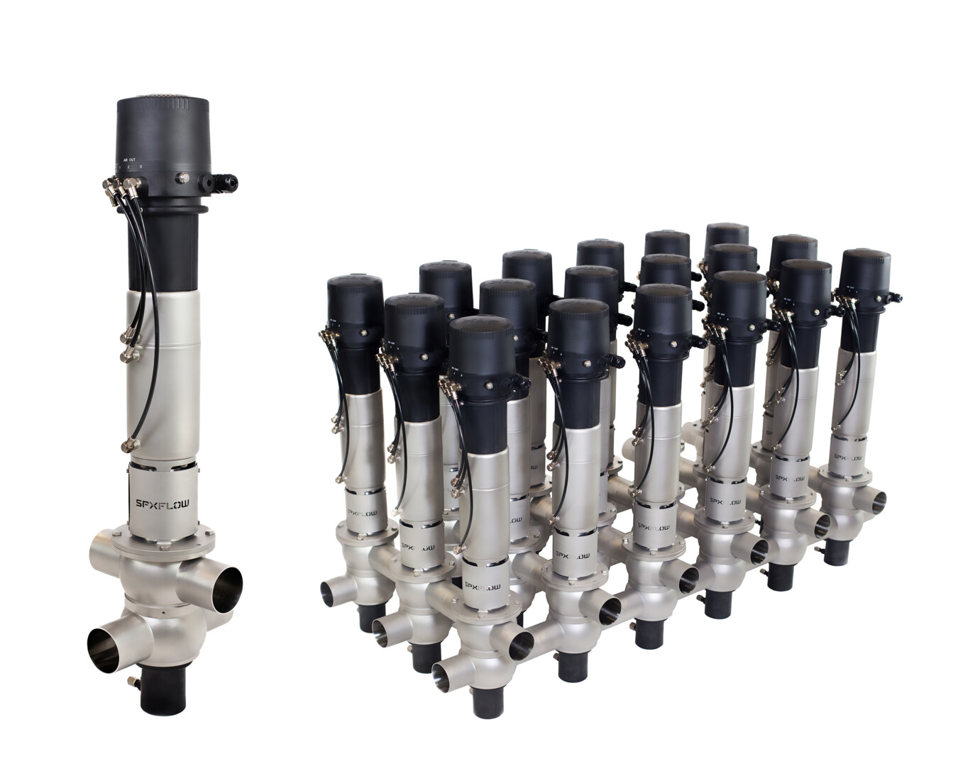

Product Type(s): Mixproof Valves

D4
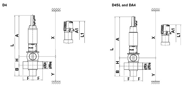
| Dimensions mm | A | A1 | B | øDa | øDi | F | H | L | L1 | X* | Y* |
| DN | |||||||||||
| 40 | 483 | 566 | 120 | 41 | 38 | 125 | 63 | 666 | 749 | 820 | 200 |
| 50 | 487 | 570 | 126 | 53 | 50 | 125 | 75 | 688 | 771 | 830 | 218 |
| 65 | 495 | 578 | 134 | 70 | 66 | 125 | 91 | 720 | 803 | 840 | 242 |
| 80 | 583 | 666 | 146 | 85 | 81 | 142.5 | 106 | 835 | 918 | 930 | 274 |
| 100 | 593 | 676 | 156 | 104 | 100 | 142.5 | 125 | 874 | 957 | 940 | 303 |
| 125 | 677 | 760 | 179 | 129 | 125 | 150 | 150 | 1006 | 1089 | 1030 | 350 |
| 150 | 725 | 793 | 194 | 154 | 150 | 150 | 175 | 1094 | 1162 | 1075 | 390 |
| INCH | |||||||||||
| 1.5 | 485 | 568 | 119 | 38.1 | 34.8 | 125 | 63 | 667 | 750 | 820 | 197 |
| 2.0 | 488 | 571 | 125 | 50.8 | 47.6 | 125 | 75 | 688 | 771 | 830 | 216 |
| 2.5 | 492 | 575 | 131 | 63.5 | 60.3 | 125 | 85.3 | 708.3 | 791.3 | 840 | 233 |
| 3.0 | 498 | 581 | 137 | 76.1 | 72.9 | 125 | 97.9 | 732.9 | 815.9 | 850 | 251 |
| 4.0 | 594 | 677 | 155 | 101.6 | 97.6 | 142.5 | 125 | 874 | 957 | 840 | 301 |
| 6.0 | 726 | 795 | 193 | 152.4 | 147.3 | 149.8 | 175 | 1095 | 1161 | 1080 | 391 |
*Minimum installation and valve insert removal dimensions