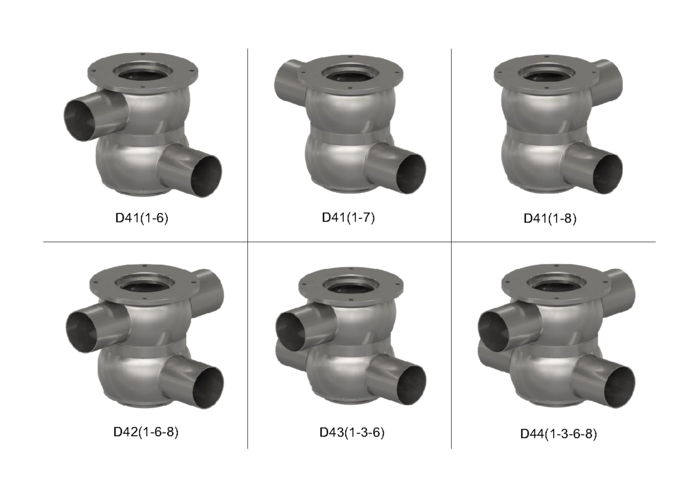
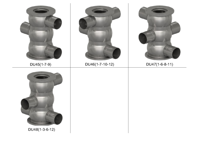
D4 / DA4 Series - Double Seat Mixproof Valves
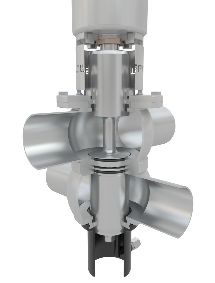
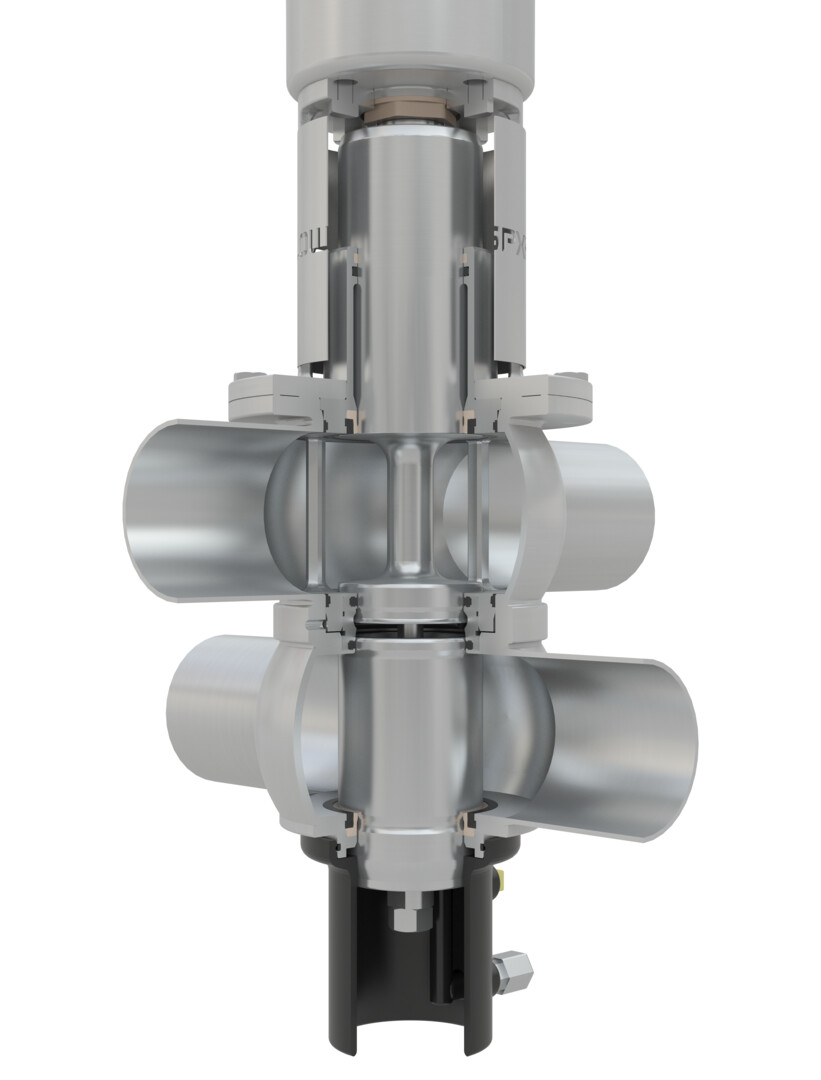

Offers reliable separation of fluids and an ultra-hygienic option for enhanced cleanability..
D4 SERIES
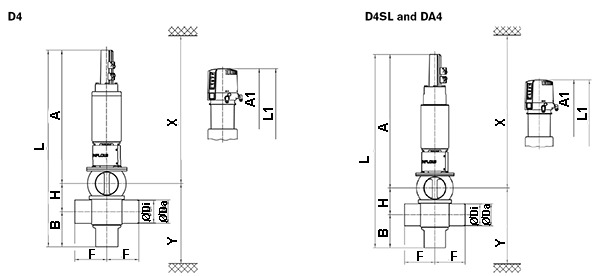
| DIMENSIONS INCH | A | A1 | A2 | B | øDa | øDi | F | H | L | L1 | L2 | X* | Y* |
|---|---|---|---|---|---|---|---|---|---|---|---|---|---|
| 1.5 | 19.1 | 22.4 | 24.9 | 4.7 | 1.5 | 1.4 | 4.9 | 2.5 | 26.3 | 29.5 | 32.3 | 7.8 | |
| 2.0 | 19.2 | 22.5 | 25 | 4.9 | 2.0 | 1.9 | 4.9 | 3.0 | 27.1 | 30.4 | 32.7 | 8.5 | |
| 2.5 | 19.4 | 22.6 | 25.1 | 5.2 | 2.5 | 2.4 | 4.9 | 3.4 | 27.9 | 31.2 | 33.1 | 9.2 | |
| 3.0 | 19.6 | 22.9 | 25.4 | 5.4 | 3.0 | 2.9 | 4.9 | 3.9 | 28.9 | 32.1 | 33.5 | 9.9 | |
| 4.0 | 23.4 | 26.7 | 29.2 | 6.1 | 4.0 | 3.8 | 5.6 | 4.9 | 34.4 | 37.7 | 33.1 | 11.9 | |
| 6.0 | 28.6 | 31.3 | 33.8 | 7.6 | 5.8 | 6.0 | 5.9 | 6.9 | 43.1 | 45.7 | 42.5 | 15.4 | |
| 2.0 Sh5 | 19.3 | 22.6 | 25.1 | 5.1 | 2.4 | 2.2 | 4.9 | 3.2 | 27.6 | 30.9 | 29.5 | 9.0 | |
| 3.0 Sh5 | 23.0 | 26.3 | 28.8 | 5.8 | 3.5 | 3.3 | 5.6 | 4.3 | 33.2 | 36.4 | 35.4 | 11.1 | |
| 4.0 Sh5 | 26.4 | 29.6 | 32.1 | 6.7 | 4.5 | 4.3 | 5.9 | 5.3 | 38.4 | 41.7 | 40.2 | 13.0 | |
| 6.0 Sh5 | 28.8 | 31.5 | 34 | 7.9 | 6.6 | 6.4 | 5.9 | 7.4 | 44.1 | 46.8 | 42.7 | 16.1 |
*Minimum installation and valve insert removal dimensions
NOTE: Add the following approximate dimension to “F” for each clamp port connection 0.5" for valve sizes 1.5" - 3.0", 0.62" for valve size 4" and 0.88" for valve size 6.0".